 GREEN
GREEN
AND
CLEAN
POWER
French River Land Company's Website!
|
AND CLEAN POWER French River Land Company's Website!
|
|
French
River Land Company's Home Page!
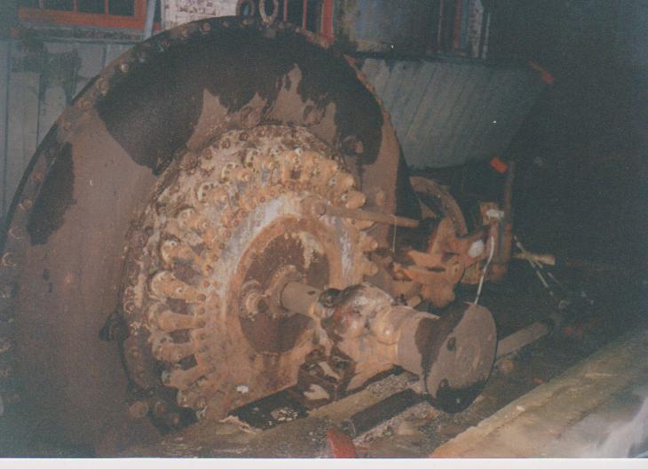
Rebuilding 120" Niles Boring Mill HYDROELECTRIC SITES: Anasagunticook Lake Dam Replacement- C.Fay & W.Fay Appleton Wisconsin Anniversary Senor Bonifettis' sites in Chile Turners Falls Generator Rewind USEFUL ENGINEERING: Admitting Air to Turbine Runners Improves Efficiency, S. Logan Kerr Air Admission to Hydro Runners, David Cox, USCOE, Kerr Dam Archimedian Screw Pump Handbook- Gerhard Nagel A Self-Adjusting Spring Bed Bearing- Henry G. Reist ASME 1646 The Banki Water Turbine Mockmoore and Merryfield Bearing Currents: Their Origin and Prevention C. T. Pearce Bishops Method- STABGM Program Blade Pitting- Boving LTD 1930 Cavitation- Accelerated Research, Allis Chalmers Research Cavitation & Vibration of a Draft Tube Cavitation- Prevention & Reduction, Allis Chalmers Research Causes & Effects of Cavitation in Hydraulic Turbines Chain Turbine by: Nguyen Minh Duy Chain Turbine Mechanics- Discussions with Duy Characteristics of Modern Hydraulic Turbines-Chester Larner Comparative Tests On Experimental Draft Tubes- C M Allen & I A Winter 1923 Design of an Overshot Waterwheel (by Carl Weidner) Design of Small Water Turbines for Farm and Small Communities Design of the runner of a Kaplan turbine for small hydroelectric power plants: Timo Flaspöhler Draft Tubes of Hydro-Electric Stations by M. F. Gubin Ejection into Tailraces of Hydropower Plants: S. M. Slisskii Erection & Alignment of Vertical Waterwheel Generator Units-R.O. Standing Evolution of Hydraulic Prime Movers-Byron McCoy Fall Increaser Herschel Venturi Tube Fall Increaser Moody Ejector Turbine Fall Increaser Hydraulic Jump Apron Generator Shaft Design Calculation- Olav Hodtvedt Governor Theory for the Plant Operator Graphics of Water Wheels- William Fox Hydraulic Motors- M. Bresse & F. A. Mahan 1869 Hydraulic Power Transmission by Compressed Air Hydraulic Rams their Principals and Construction by J. Wright Clarke Hydraulic Turbine and Governor Field Erection Information Hydraulic Turbines- Robert Long Daugherty Hydraulic Turbines by Arnold Pfau Hydraulic Turbines Gelpke & Van Cleve Hydrokinetic Energy in Massachusetts, William D. B. Fay HYDROTURBINES DESIGN AND CONSTRUCTION N. N. KOVALEV Impulse Turbines by Ely Hutchinson Interference fitting a large runner shaft Kaplan Blade Design NACA Air Foil- Report No. 460 Kaplan Blade Design NACA Air Foil- Report No. 628 Kaplan Design Marko Kogovsek.xls A Laboratory Study to Improve the Efficiency of Crossflow Turbines- N. Aziz & V. Desai Loading Vertical Thrust Bearings R. C. Johnson Low Head Hydroplants, Emil Mosonyi Meggering Earth Resistance Motors as Generators for Microhydro, Nigel Smith Operation & Maintenance of Hydro-Generators Out Gassing of Cross Flow Turbines Parallel Operation of Turbines Analysis Powerhouse Design- Miniwatt Hydro Rack Design-Chicopee-Olav Hotvedt Rack Design- Hydraulic Institue of Munich Rack Design-Flow Induced Vibrations Selecting Hydraulic Reaction Turbines BUREC Snows Improved Water Wheel Governor Standard for Hydraulic Turbine and Generator Shaft Couplings and Shaft Runout Tolerances Stoplog Structure Design Calculation Stress Analysis of Hydraulic Turbine Parts, BUREC- F.O. Ruud Some Fluid Flow Characteristics of a Cross Flow Type Hydraulic Turbine- Durgin & Fay Technology of Heavy Electric Machine Building HydroGenerators Tenth Census of the US, 1880, Water Power of the US, Part I- Professor Trowbridge Tenth Census of the US, 1880, Water Power of the US, Part II- Professor Trowbridge Tests on a Kaplan Hydraulic Turbine Theoretical Conditions Related to an Open Channel Flow Linear Turbine- Ishida & Service Theory of Turbines- De Volson Wood Tidal Energy for Hydroelectric Power Plants by L. B. Bernshtein Treatise relative to the Testing of Water-Wheels and Machinery, James Emerson 1879 Trash Rack Differential Equations 2L/3 Trashrack Differential Equations General Solution f(x) Turbine Water-Wheel Tests- Robert Horton Turgo, A High Speed Impulse Turbine- Paul Wilson Water Hammer and Surge Tanks G. V. Aronovich Water Hammer-Lorenzo Allievi-Text Water Hammer-Lorenzo Allievi-Figures Water Hammer-ASME Symposium 1933 Waterpower Engineering-Daniel Webster Mead Water Turbines Contributions to Their Study, Computation and Design-S.J. Zowski TRADE CATALOUGES: ASEA- Bearings for Large Vertical Hydro-Electric Machines Bradway Turbine (progressive gate) Christiana Machine (register gate) Electric Machinery Company (EM) General Electric- Standard Specifications for Hydro Thrust Bearings and Runners Head Gate Hoists- S. Morgan Smith J & W Jolly (cylinder gate) Lombard Direct-Connected Oil Pressure Governors Bulletin N0. 113 October 1st, 1912 Lombard Governor Company Type T Instruction Book Lombard Governors for Waterwheels and Steam Engines-1902 Lombard Water Wheel Governors Catalouge 26 Ridgway Perfection Water-Wheel Vertical Shaft Water Wheel Driven Generators- General Electric Westinghouse Small Vertical Waterwheel-Driven A-C Generators, July 1944
Links:
Small Turbine Manufacturers Websites: www.waterturbine.com
|
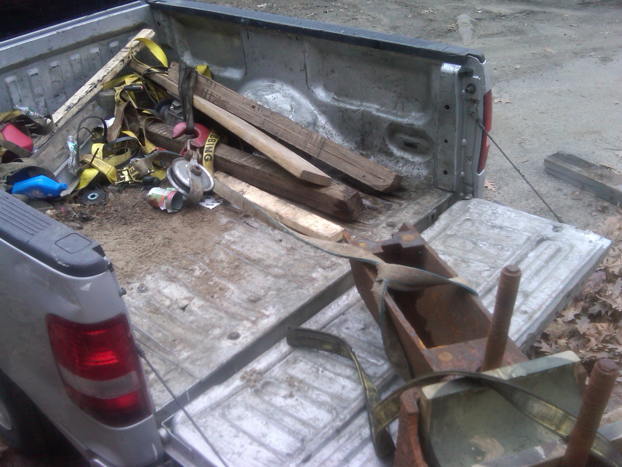
Previous Pictures Two Web Page I posted too many photographs on the website. It was becoming very slow to load. I moved some of the previously posted photographs here.
Here is a rare picture of me welding the giant bridge beams in the forebay at Woronoco Hydro's intake. When we purchased the plant we found the wooden support members were totally rotten. We chose to replace them in steel. We ripped the entire structure out. I found some scrap, 36" deep, bridge beams. Here I am welding the upper beam to its 2" diameter bed pins. We cut the beams to fit the 48 foot width of the intake. In order to support the beams we drilled into the concrete, three foot deep, by 2 1/2 inch diameter, holes with my trustee Thor Rock Drill. The holes were drilled in the location of the four corners of the beam. We used a sledge hammer and drove in the two inch diameter, solid steel, pins in the holes. We then lowered the beams down onto the pins and welded them in place. We installed three beams. One at 1/3 the distance from the bottom, one at 2/3 the distance from the bottom and one at the top. The left over pieces we cut to fit between the backside of the main beams and the concrete wall. I am standing on one of the short sections. Note the one pin you can see sticking out of the wall to the right of where I am working. I know this was over kill, but I have learned that big, is better, in the hydro industry!!!
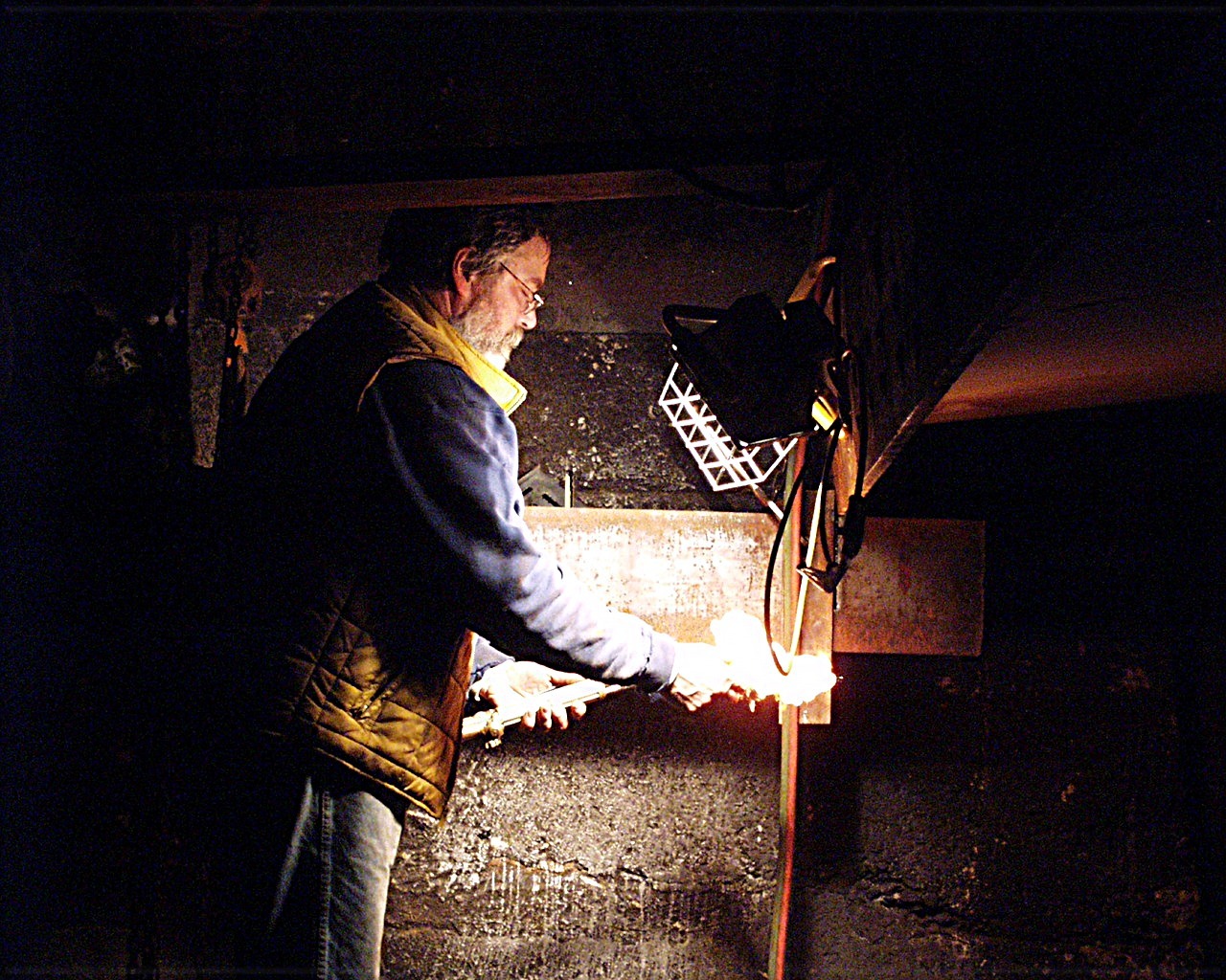
Another picture of me in my winter beard. I am lighting off one of the big Victor wrecking torches. Things get really cold on the Westfield River in December. One day we went out to work. It was dead calm and the temperature was 31 degrees Fahrenheit below zero. Our breath was coming out of our mouths and a little cloud would form and turn into miniature snowflakes!
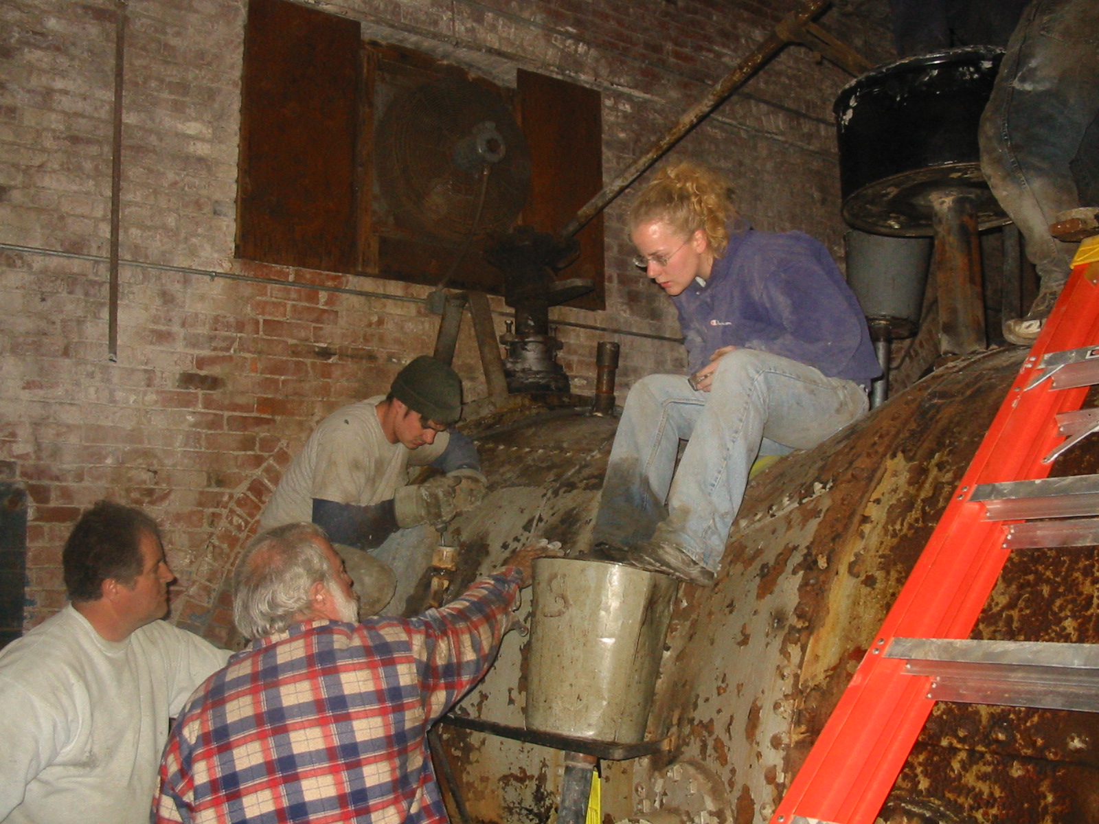
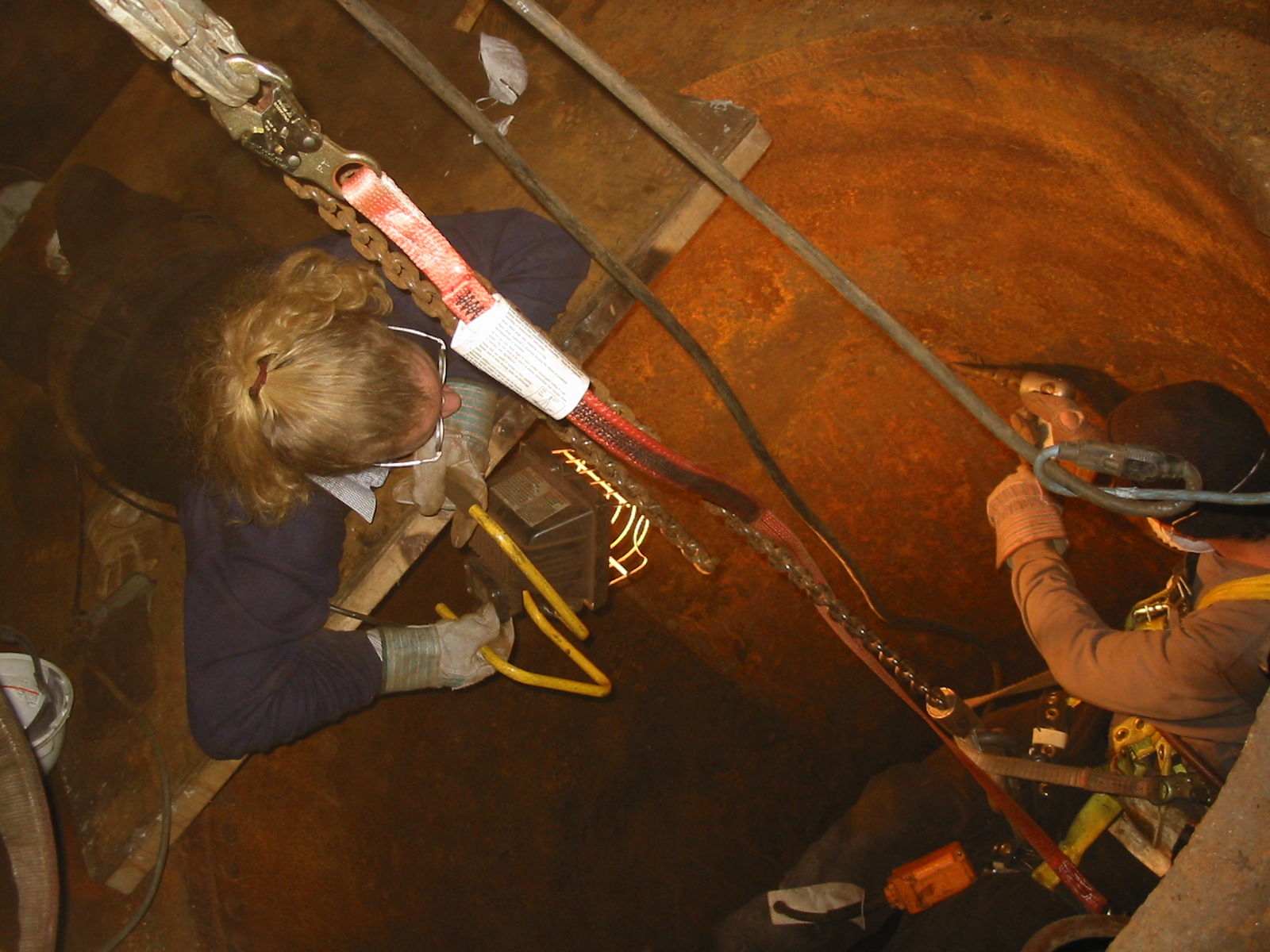
Celesty in action!!!! She is sitting on the Woronoco No. 2 pressure casing. Note the operator for the 72 inch butterfly valve over Mike's head. The crew is grouting the space between the old pressure case and the new steel plate liner. The waste paper basket is welded to a two inch pipe that is inserted between the two layers. See the second bucket located behind Celeste. We mixed the grout, emptied it into the buckets and vibrated it into the cavity.
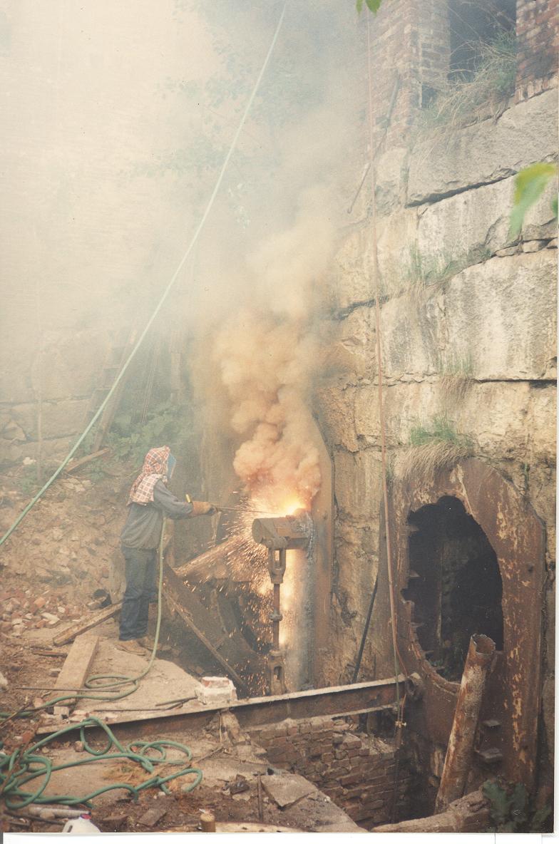
Removing the Rodney Hunt turbines at Livermore Falls, N.H. Bill Fay is using thermite bars to burn the 3 inch thick cast iron head covers at Livermore Falls. Here the cold of outer space (liquid oxygen at minus 297 deg F) is feeding the fires of hell (OxyAcetylene burns steel at 2500 deg F, the surface temperature of the sun is 16,000 deg F. The tip of the thermite bar runs 8,000 deg F). The thermite bars are consumed like a punk stick. As they burn down the 8,000 deg F gets very close to your hands!! Once they are ignited, we could carve our initials in solid granite. (Livermore Falls<<click here for Livermore Falls)
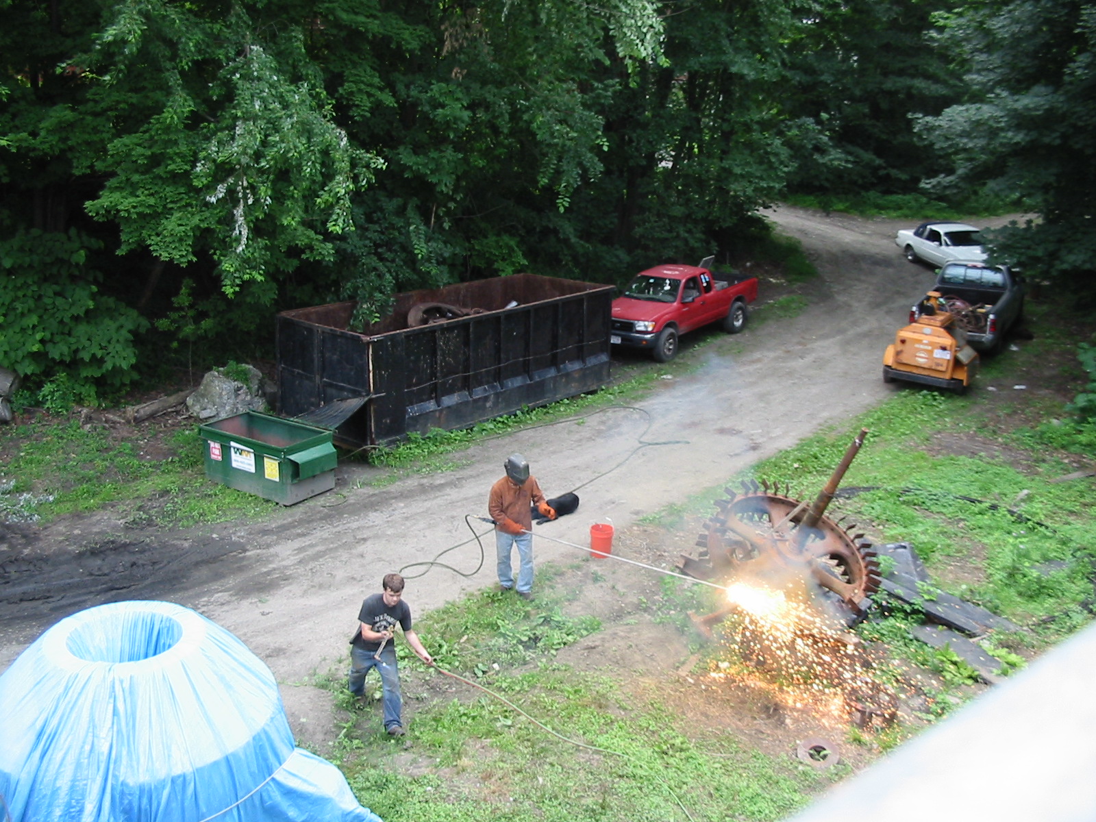
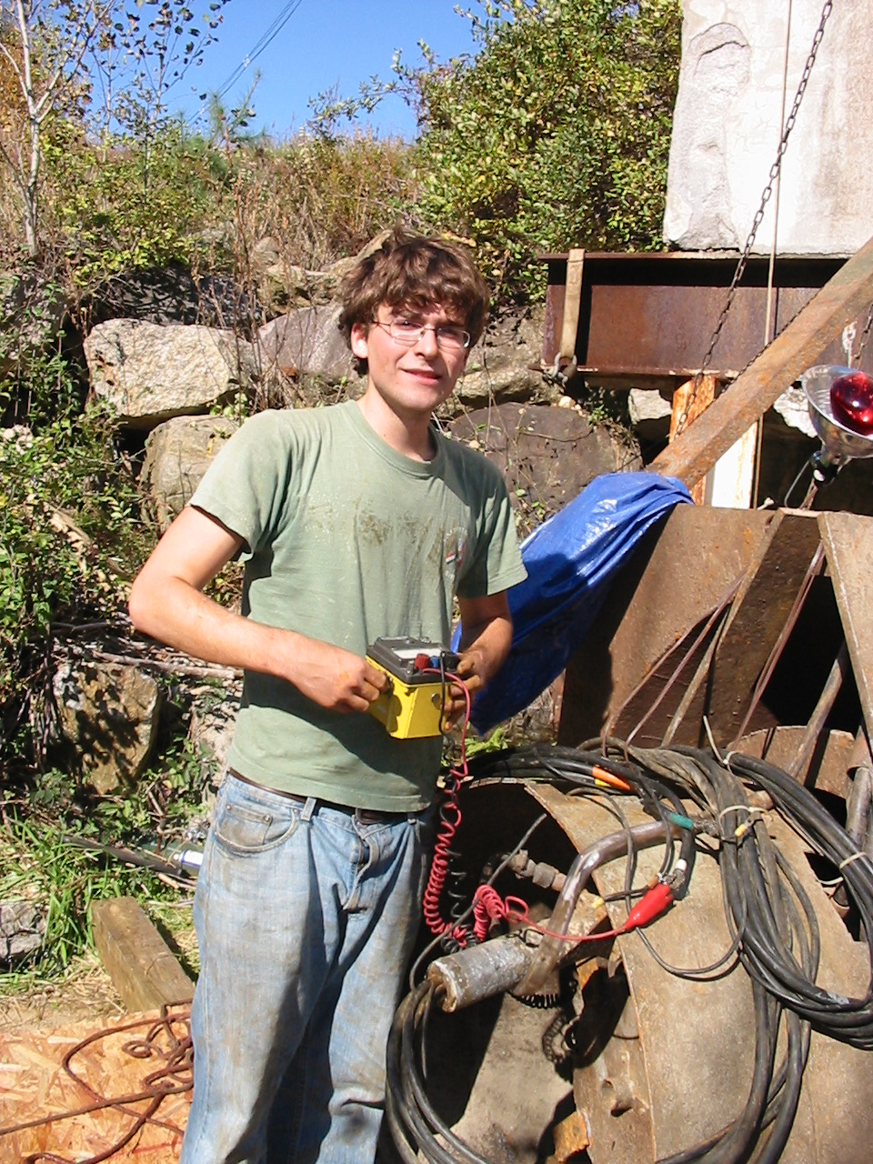
Here, I am using thermite bars to burn the salient pole rotor off of the Westinghouse shaft. We needed the shaft to make our hybrid WestFang Generator. The rotor had sat outside in the weather for so many years, that we were afraid of bending the shaft, if we pressed it out of the flywheel bore. Ronnie Johnson has just lit up the end of the bar with the 30 inch wrecking torch. Once the bar starts to sputter, you crank open the ball valve, on the collet holder and all hell breaks lose!! It never ceases to amaze me how destructive a thermite reaction can be. Kids don't do this at home!!
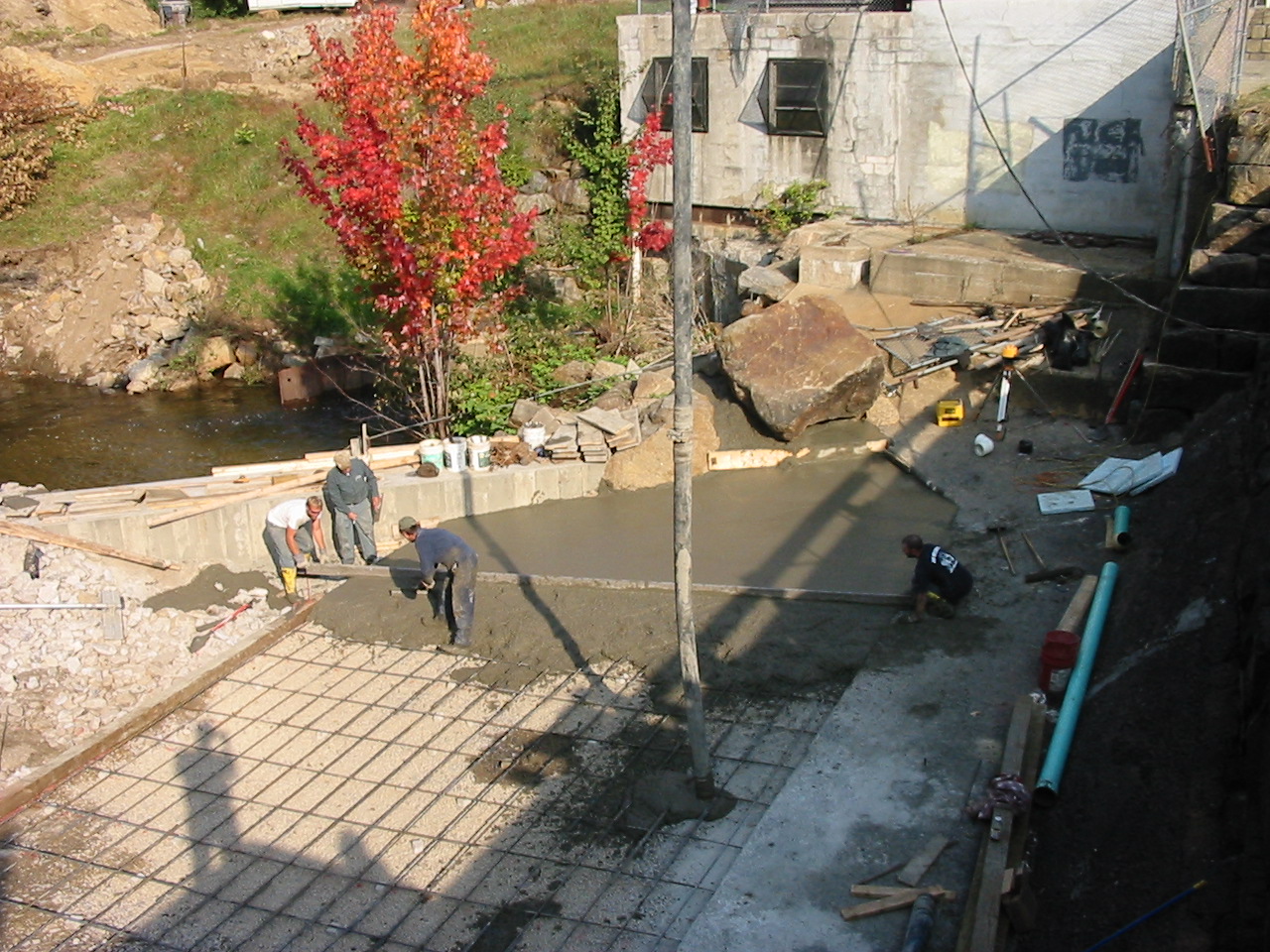
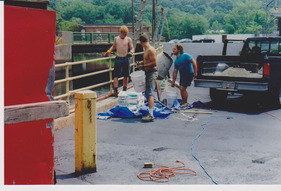
Golden Pond Hydro Powerhouse, Fall 2008, Pouring the spillway apron extension. The large rubber hose is the "elephant trunk" that is connected to the concrete pumper. We poured over 100 cubic yards of concrete. Our hearty thanks to Steve Doyon, of the New Hampshire DES, Dam Safety Program and Director Peter Valeri, of the FERC's, New York Regional Office for their technical help and support in repairing our project!!
We have the following generators for sale. Please e-mail me at bfay@frenchriverland.com We have two of these General Electric, 800 KVA, 640 KW, 200 RPM, 2300 volt, horizontal, salient pole generators for sale. They are in very good condition and were taken out of service 3 years ago. They are in safe storage in Butte, Montana. We are asking $25,000, per generator, fob Butte, MT. Please call me at 413-427-2665, Bill Fay Please click on this Picasa Web Album Address for more photos: http://picasaweb.google.com/frenchriverland/MissoulaMT?authkey=Gv1sRgCNn7tZPspb3PvwE#
A rare picture of Celesty, Will and Ronnie with the famous Mr. William Munch. Bill is a master electrician, hydro developer and owner of the Valatie Falls HEP. He learned about hydro development as a child. He worked with his father developing hydro stations in the 1930s and 1940s. I am always in awe of Bill Munch and see him as a living part of hydro history. By the way, he hates to have his photo taken!!!
Celesty and Will during the presentation of their WPI Major Qualifying Project (MQP). These gentlemen are their advisors, Professors Mingjiang Tao and Paul Mathisen. They designed a replacement dam for the Anasagunticook Lake Dam in Canton, ME. Celesty has graduated with a BS Degree in Civil Engineering. Will is graduating this Spring with a BS Degree in Civil Engineering. Please see the following link to their paper: Anasagunticook Lake Dam Replacement- C.Fay & W.Fay<<< click on link
Celesty torquing down the little bull gear bolts for the main driveshaft at Slater Mill Museun in Pawtucket, R.I. The Wizard is watching for movement of the blocks. This exhibit always had a severe vibration problem. This was partially caused by the replacement, main, bullgear located in the basement. When it was cast, it cooled in a slightly oblong shape.
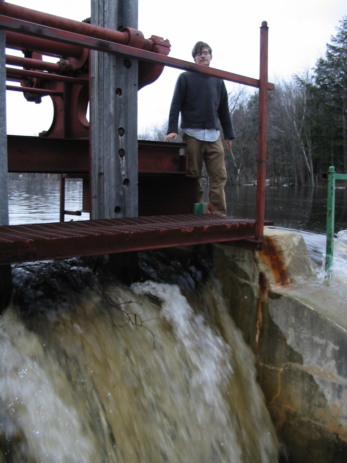
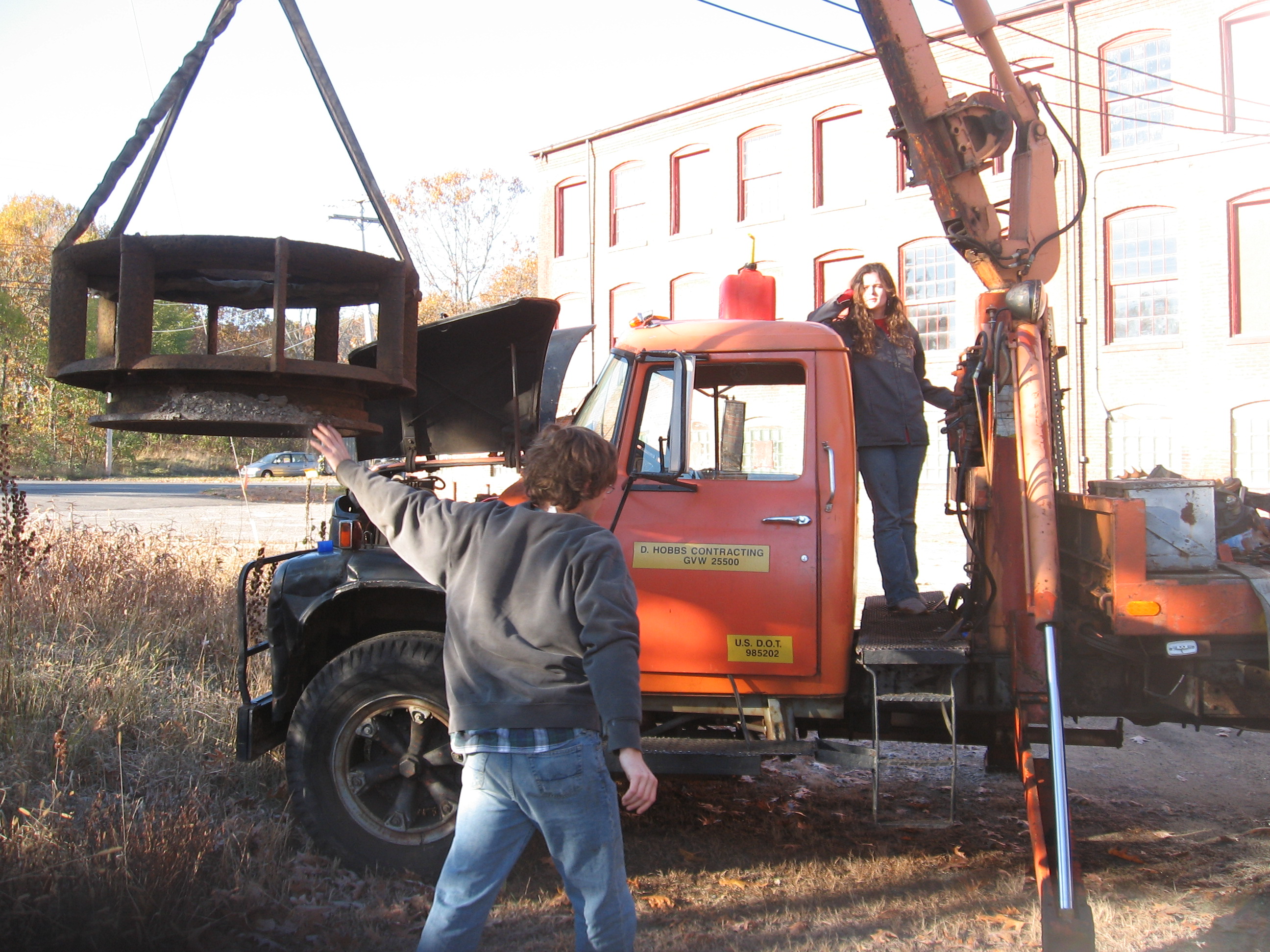
Will operating our flood gate during the freshet of April 9th, 2005. See the photo essay of how we replaced this enormous (8 foot by 10 foot) wooden gate without the aid of a crane: Please see the attached Picassa album (click on the box below):
Mike is scaling the inside of a draft tube whilst Celesty holds the halogen light for him. This is a really tall tube. Mike is about 18 feet above the tailwater. The tube is about 8 feet in diameter at the high side. We had him tied on with redundant safety belts and chains.
Celesty checking out the Lower Bristol site in April of 2005. She and Will almost bought the upper and lower sites. This powerhouse and its equipment have since been obliterated from the face of the earth. What a shame. February 5th, 2009 added Sparhawk Mills
Celesty supervising the pick, of the Brockway Mill's, second generator rotor. The first generator lost its bearings and destroyed its rotor and iron core. Chris purchased this generator. He dropped both rotors off at the shop. We pressed both shafts off the rotors. We turned down the old shaft and pressed it back into the new rotor. We did this so the generator shaft and coupling would match up to the existing turbine. Note the newly glyptoled salient pole pieces.
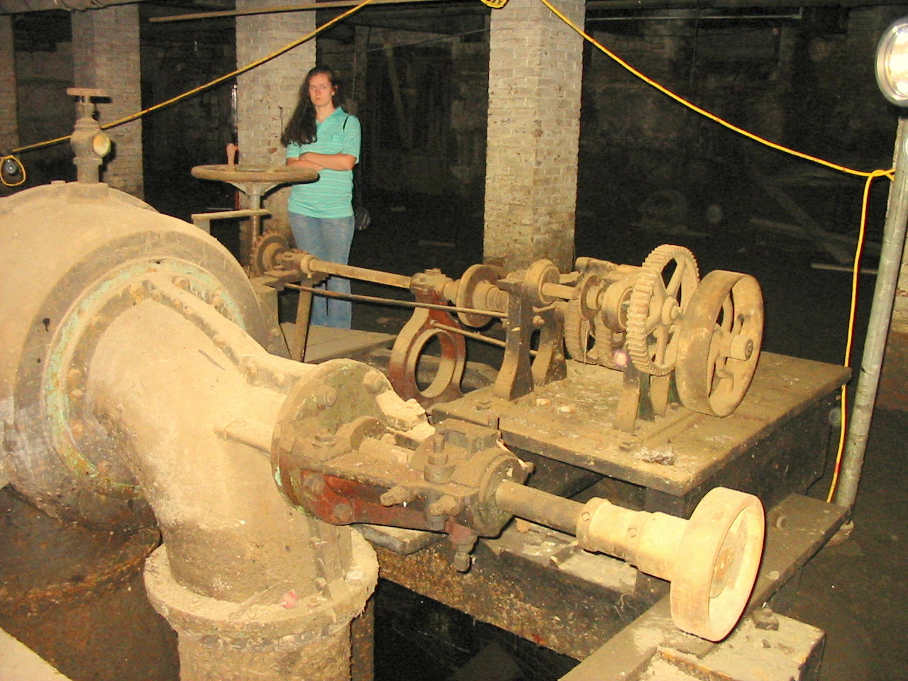
Mary Remington deciding if the old Bradway is worth rebuilding. Poor Mary, instead of going to the movies, she gets to see defunct hydroplants, in the basements of old cotton mills!!! Actually, she really enjoys the trips. This is a Bradway Waterwheel and Governor, both the turbine and governor, were designed by Charlie Bradway. This site has 54 feet of head. (see additional photos at end of Bradway webpage)
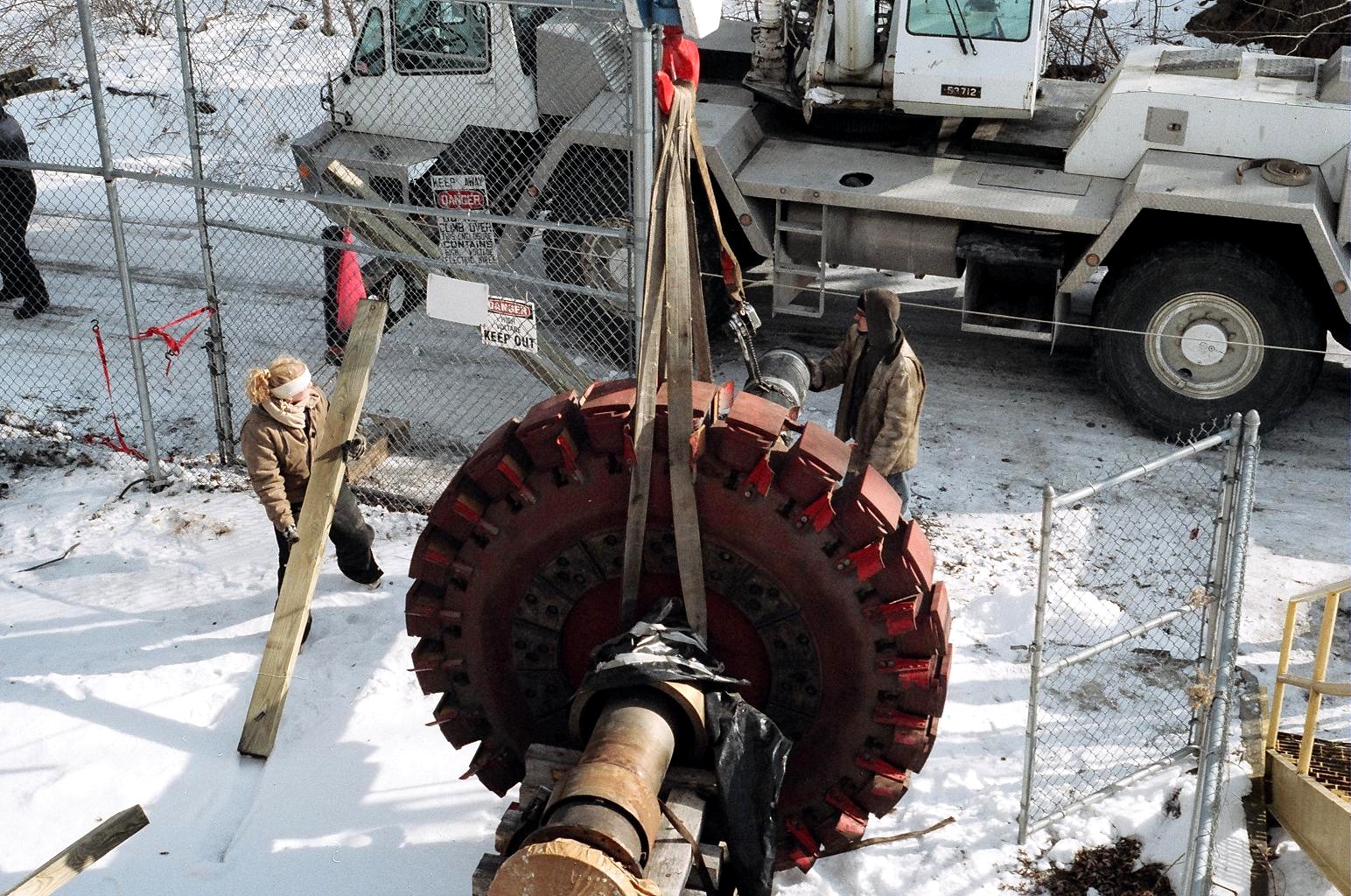
Celesty, Davis and Mike rigging in the 26,000 pound, solid steel, Dong Fang synchronous, salient pole, rotor. Notice Celesty's mitten stabilizing the rotor shaft while Davis and Mike remove the cribbing. This is typical!!! We can not work in or near the water unless it is 10 below zero!! Celesty is always in the thick of it!!! At least she was smart enough to wear her Carhart thermal coveralls. See the third to the last photo, in the machine shop sidebar, to see how large this rotor really is and to see it flying through the powerhouse!!!
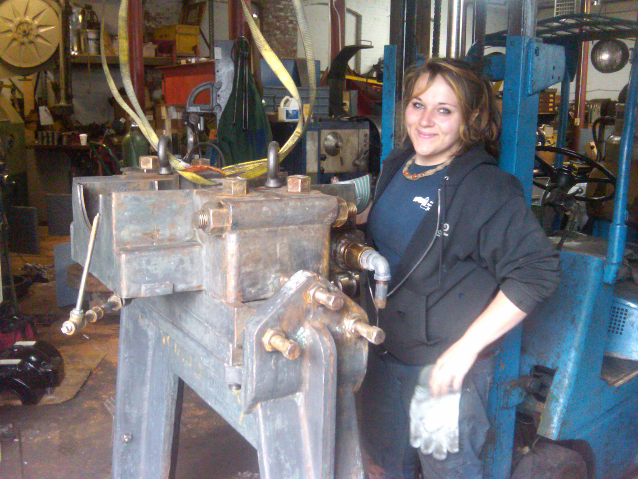
A second view of Celesty and Mike picking the Dong Fang rotor. Celeste is tossing those 70 pound, southern yellow pine, timber cribs, around like they were match sticks!! Between working with us building hydroelectric plants, for the last 12 years, and graduating with a Civil Engineering Degree from WPI, she knows more about hydropower engineering then most 50 year old consultants!! December 20th, 2008 added our adventures rebuilding the Valley Paper Company's Smith Kaplan in 1993. December 12th, 2008 added a link to the CORPS's Water Hammer Program for penstock transients November 26th, 2008 added Carl Weidner's Design of an Overshot Waterwheel( an exquisite paper) November 24th, 2008 added barrel stave bearing repair webpage November 1st, 2008
repaired Bradway page and added Golden Pond Repair Photos. Will Fay is using a megohmeter to check the primaries for short circuits. We found out that one of the high voltage primaries had short circuited to ground inside the aluminium tube that you can see the wires passing into. This tube was designed to keep the high pressure oil inside the turbine and the water from entering the turbine. It turned out to be a complicated design. We had to destroy it in order to reverse engineer it. It was filled with epoxy. The wires were interrupted by brass cylinders that had been drilled from either end that created blind holes with brass in between. The wires were inserted from either end and silver soldered in place. They were then inserted in the aluminium cylinder and it was filled with epoxy. This elaborate scheme was to prevent the high pressure oil from wicking up the interstices of the cooper wire.
October 6th, 2008. Added Bradway Turbine webpage. September 30, 2008: I spent a lot of time finishing up our saga about removing the turbines at Livermore Falls, NH. You may thoroughly enjoy perusing the web page: http://frenchriverland.com/livermore_falls.htm
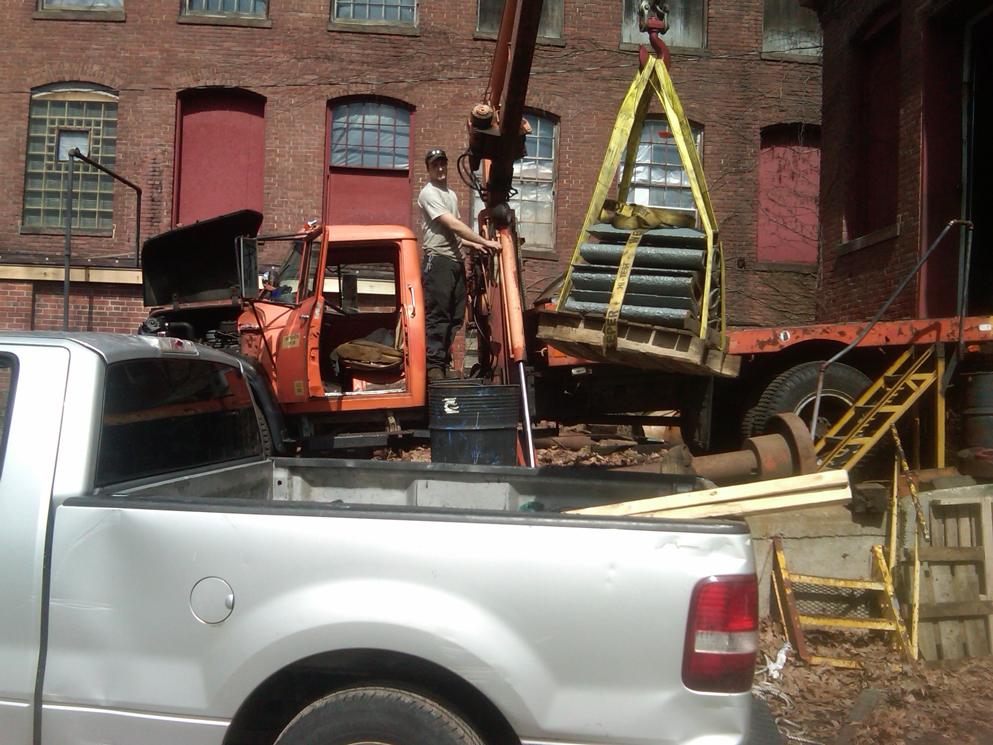
Mary Remington and Will Fay offloading one of four, Rodney Hunt, Hi Test, gatecases. These units are part of a quadraplex, dual camelback unit similar to Jim Beesha's units at Mechanicville, N.Y.
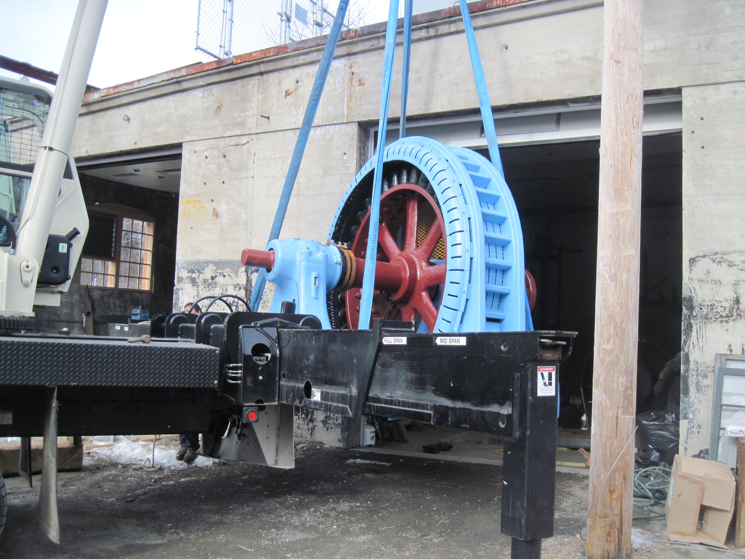
Flash!!! March 12th, 2008, 2:00 PM. We just synchronized Woronoco No. 1 for the first time in 23 years. We got the unit up to full gate and made 460 kilowatts. This was very good considering the tail water stage is elevated by ten feet. The rooster tail coming out of the gorge is so large it is flowing 400 feet across the tailrace pool and hitting the far shore!!!We have been rehabbing the unit for the last nine months. It is better than new!!! Note the disc brake and new hydraulic power pack. Woronoco No. 1 Rebuild <<<<<<< click on the hyperlink
How do you move a 44,000 pound generator through the powerhouse door with no overhead crane? See the sidebar or click on the below link:
No. 2 generator going through the powerhouse door!
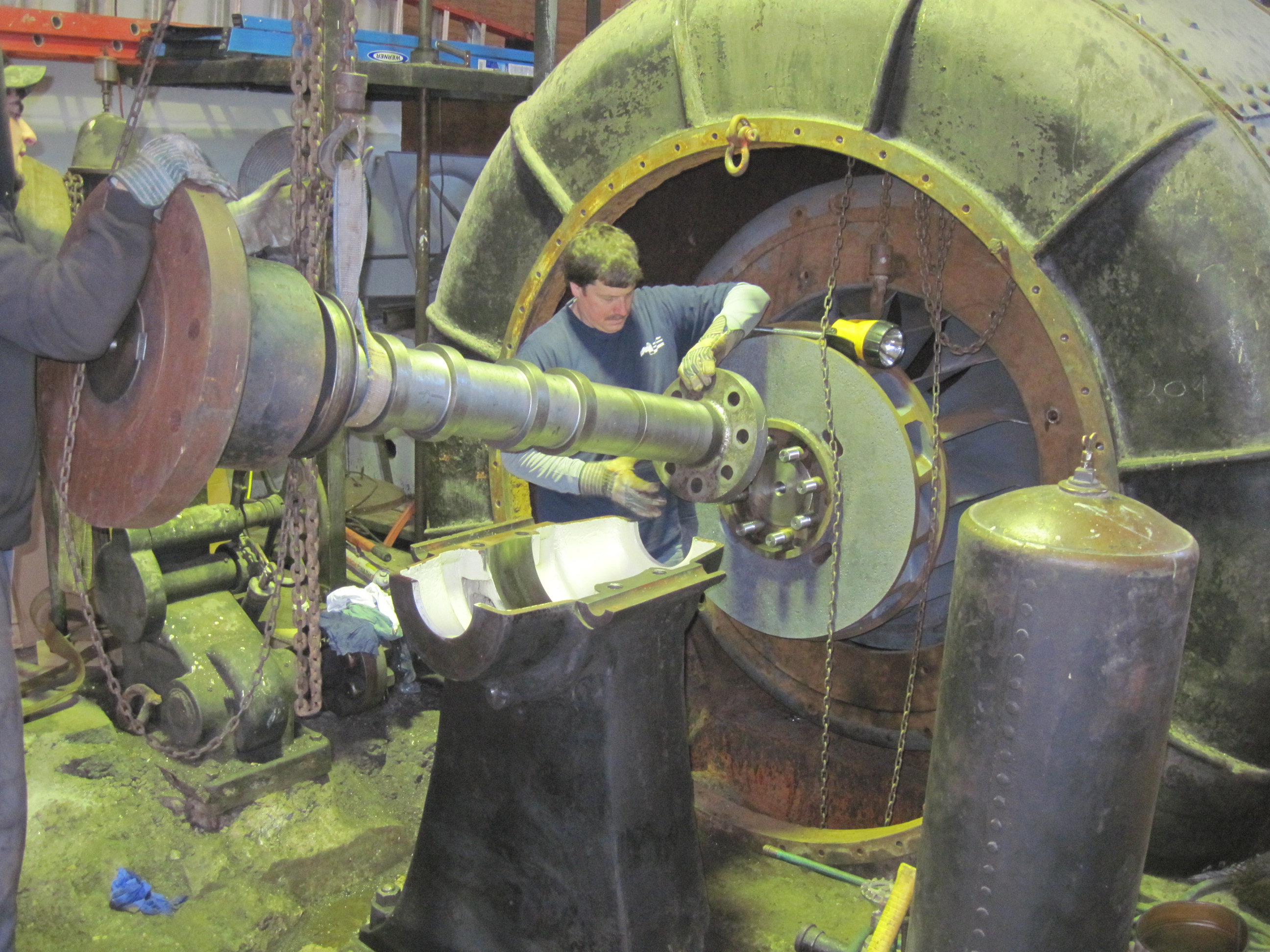
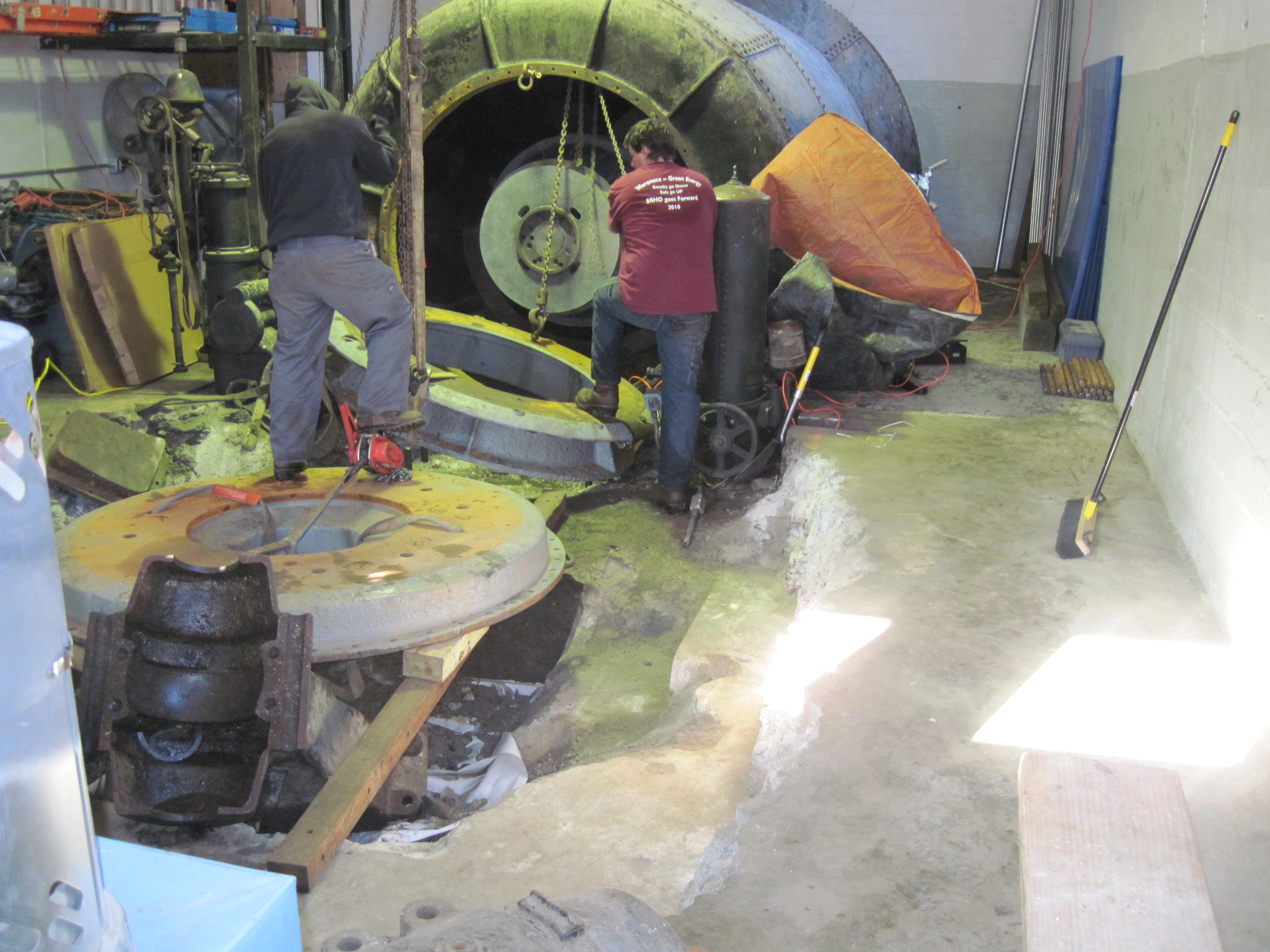
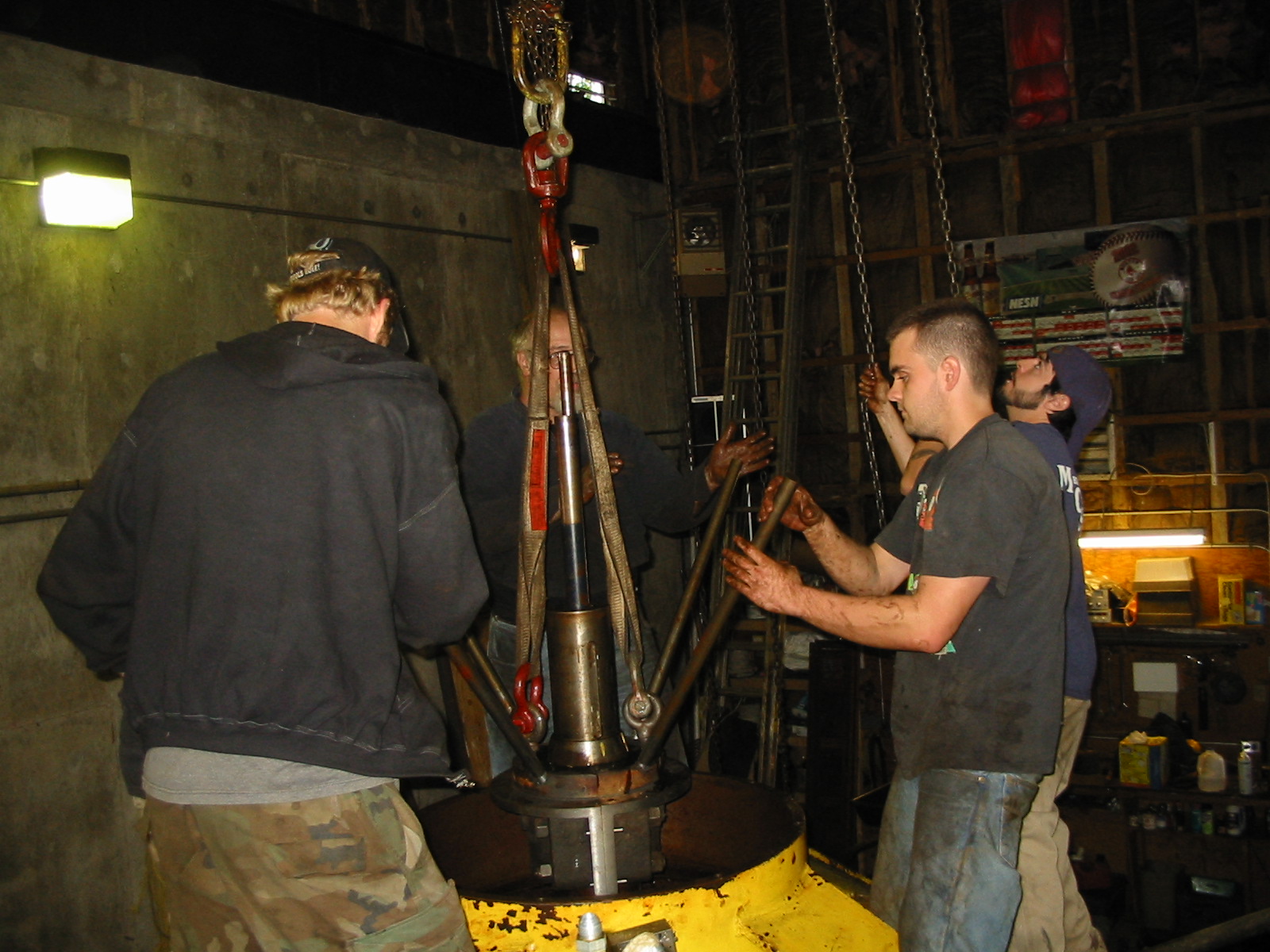
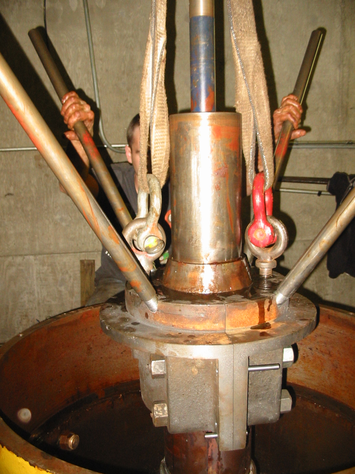
Here we have installed the 8, 1 1/2 inch, studs into the end of the runner. We are inserting the main thrust shaft into its bore. We have cleaned and painted the oil chamber of the thrust pedestal. We are making our final axial adjustments to the runners to insure a tight seal between the runner skirt ring and the throat ring bore.
Here we have inserted the double runners into the pressure casing. We are installing the outer throat ring to make a final alignment of the runners on the main shaft. I spent 6 hours cleaning up. Ironically, my Mother always told me to "get a college education or I would end up sweeping floors"!!! Ah well, the president of the company must stay useful!! It is nice to have the windows buttoned up, lights on the ceiling and heat in the room. Tomorrow we clean the thrust pedestal, install the rebuilt thrust bearing, and thrust shaft. We will bolt the thrust pedestal to its bed rungs and bolt the thrust shaft to the end of the runner spool. We will then use the 50 ton port-a-power to axially adjust the location of the two runners to align with the tips of the inboard and outboard wicket gates.
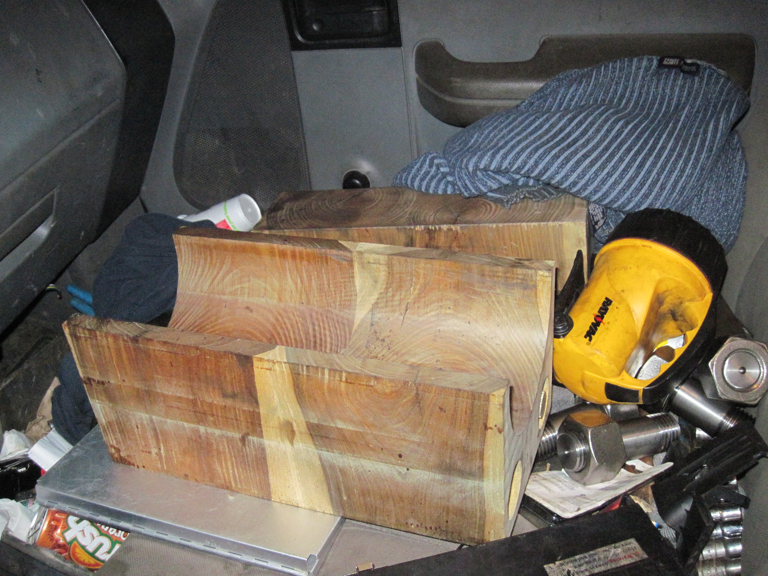
Here are the outboard and mid span lignum vitae bearings fresh from the machine shop on the front seat of my truck (Its three years old and I just turned 190,000 miles). These bearings need to be made with the end grain facing the shaft. We can not obtain blocks thick enough to do this in one piece. We cut several blocks to make the length. We precision machined the ends. We linearly drilled through their axis and through bolt the blocks. We coat the ends with Gorilla Glue before we tighten the tie rod bolts. Adjacent to the blocks are the new coupling studs that hold the thrust shaft to the butt end of the runner spool piece. Margie Bailey made these from 1 9/16" ground and polished stock. Weirdly, the coupling holes were 1 9/16" diameter. Warren wanted to buy a bastard 1 9/16 tap off of E-bay. I said no! Drill and tap the holes in the runner 1 1/2-6. Make the studs from 1 9/16" stock. Turn the ends down and thread them to 1 1/2-6 to make oversize/standard ended studs to fit the bastard holes! and that is exactly what Margie did!!!! Margie is turning into a great apprentice. We have sent her to night school to learn machine shop practice at the local Vo-Tech.
The smaller of our two generators arrived at Indian River HEP today. It was pretty impressive seeing it going along the mountain road. Please see: http://picasaweb.google.com/frenchriverland/No2GeneratorArrivesOnSite#
October 3rd, 2010, please see the side bar on our efforts to rehabilitate Tannery Pond Hydro.
September 12th, 2010, Celesty and Ron rigging the new draft tube down the hole in the powerhouse floor at Tannery Pond. The Type 80, Rodney Hunt gearbox and generator are seen in the background. On Monday we took delivery of the little GE vertical waterwheel generator that Tony Rossario rewound and replaced the iron stacks for us.
A view of the two new draft tubes purchased with an MTC Grant for our powerhouse at Tannery Pond. The grey tube is for the Leffel 17 A turbine. The brown tube is for the Leffel 18 Z.
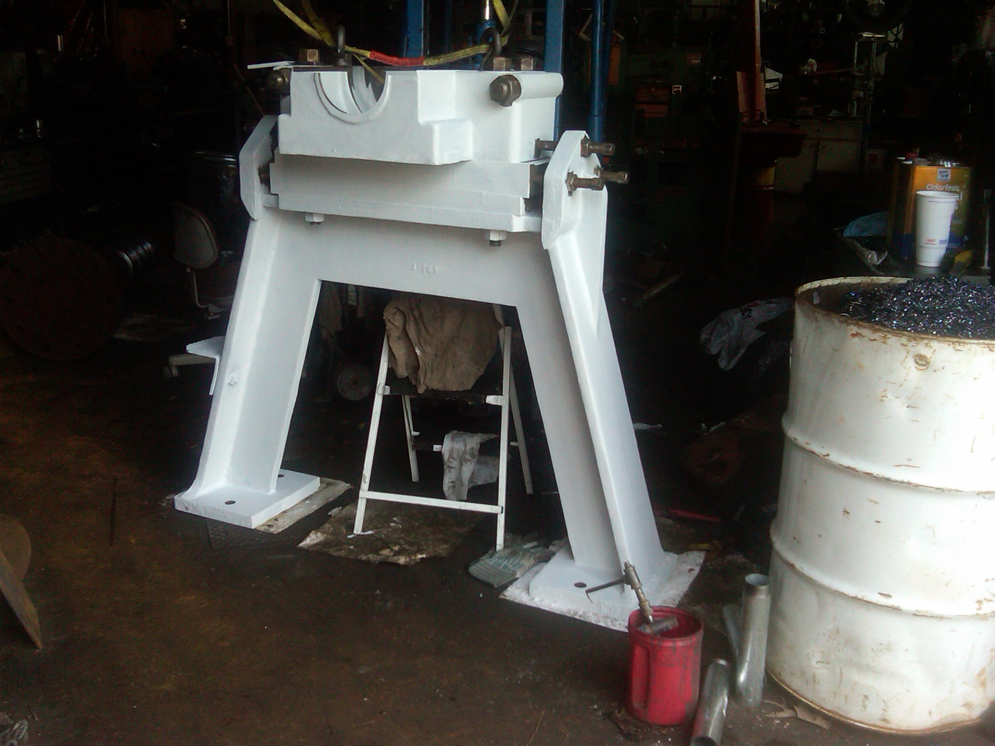
The "Wizard", Warren Fay is fabricating the new disc brake for Indian River's No. Two Turbine. At the moment it is superfluous, because the turbine gates are so tight, that the unit stops moving when we shut down the wicket gates.
Margie has just wiped down the thrust bearing in order to apply a coat of paint. You can see the cover to the stand in the left foreground. We paint the inside a cream colour so that we can detect any contaminants in the oil.
Marge Bailey has been cleaning and painting the thrust bearing stand from Montana.
Here, Mike Farrel is loading another set of re-conditioned wicket gates into the bed of my trusty FORD F-150. It just turned 200,000 miles. I have driven almost to the moon!!
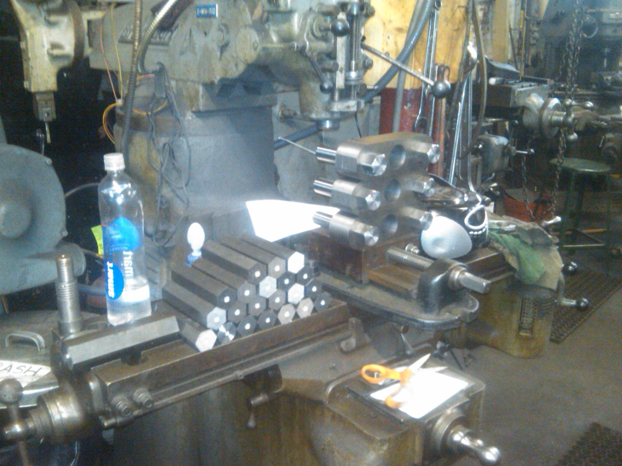
A set of wicket gate links and pins for the 43 inch Leffel Type "F" our No. One Turbine at Indian River. The hexagonal blanks are for the nose bolts. We fabricated the links out of cast iron dura-bar.
Fabricating Leffel wicket gate links from a piece of cast iron dura-bar. As Mike Farrel slowly turns the rotary table, he is machining the outside radius of the links. The flame cut pieces were too hard and was quoted at $3200 for 24 rough blanks. The dura bar is more brittle and cost $500 for the equivalent amount of material! We used the dura-bar. The two end holes are for the wicket gate nose bolt and the eccentric pin. The middle hole is provided so that the cast iron pin will crack in 1/2 if anything gets jammed between two adjacent wicket gates. The links are much cheaper then the wicket gates!!
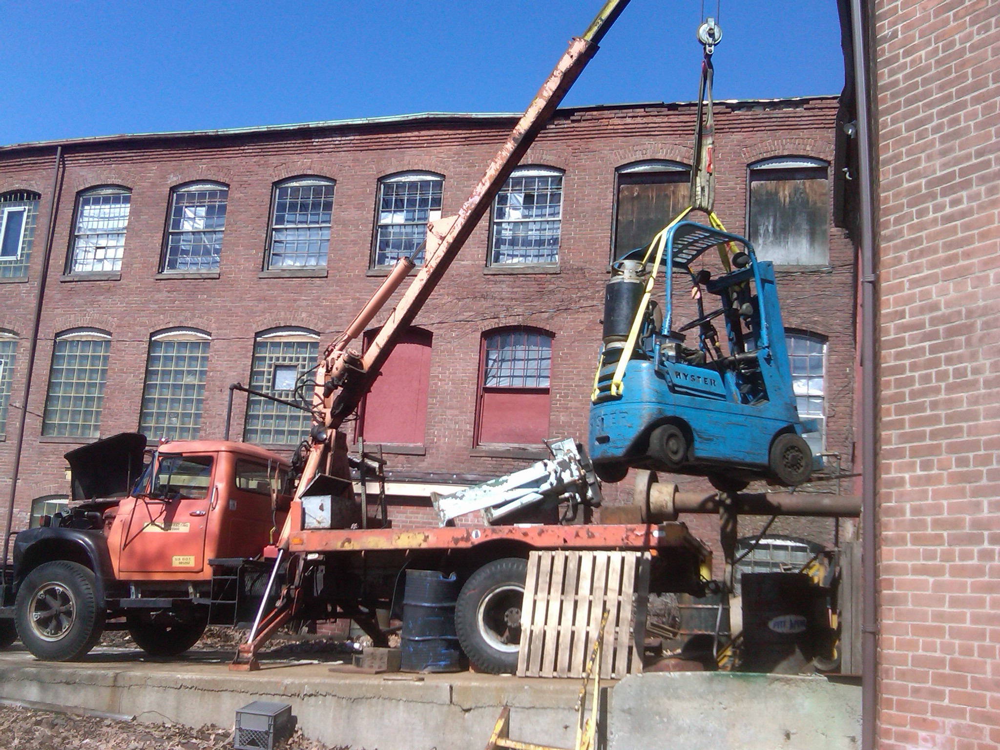
Davis purchased all the chain fall trolleys and all the chain falls from the ruins of the Pepperell Paper Company. He needed the forklift truck to remove them from their I-beams. Here, I am lifting the Hyster from the shop doorway onto the trailer for transport to Pepperell. In the background you can see the Indian River No. One Unit's thrust stand and the No. One turbine's intermediate shaft. I did a tune up on the old gas 392 and it is purring like a kitten! I dropped one of the two point screws down inside the distributor and I had to pull the distributor to get the screw back!
April 6th, 2011, Hi Everyone!! Our Indian River No. 2 Unit was synchronized today, to Western Mass Electric Company's grid, for the first time in 19 years. We were at a gate setting of 28 % and we were making 98 kilowatts. The electrical engineers from WMECO were still doing the relay witness test. It will take a few more days to cautiously bring the unit up to full power. It is very smooth. When we shut it down, the wicket gates are so tight that the unit stops rotating with out the brake. Warren is still making the brake disc. The large unpainted I-beams in front are provided to solidly hold the brake calliper. We now start in earnest on Unit No. One.
March 29th, 2011: Disaster struck at 4:30 am!!! My birthday present!! March 29th, 2011. Our $ 117,000 stainless steel runner has totally cannibalized its gate case!!! In 34 years of hydro dealings, I have never seen such a scene of destruction. The stay vanes are gone! The wicket gates are gone!!! 1/2 of the 9 foot diameter crown of the gate case is gone. The stainless steel runner has chewed up the cast iron giant pieces and spit 4 inch chunks into the tailrace like a glorified garbage disposal!!!! A runner made of any other material would have vaporized!!!! Kudos to the great engineers of American Hydro who designed this incredible piece of machinery!! Please see their website at: http://www.weirpowerindustrial.com/products__services/american_hydro.aspx We think one of the stay vanes broke loose and wiped out the rest of the machine. At 57, I take it in stride!! We will rebuild it with our on board resources!!! The new draft tube for Indian River, Unit One, due to its 1/2 angle, will not fit between the steel I-beams that support the new pressure casing. In order to bolt the draft tube onto the unit, we fabricated a cylindrical spool piece to fit between the I-beams. This piece is bolted to the bottom of the new pressure case. Its length is such that its bottom flange projects three inches below the bottom flanges of the pressure casing support I-beams. The draft tube is then bolted to the bottom flange of the spool piece. Here we are machining the surface of the flange flat and parallel to the opposite flange. The small triangular gussets were welded onto the bottom side of the flange to stiffen it. When the welds cooled, the stiffeners contracted and made the surface of the flange wavy. Warren, our mechanical/machinist Wizard is restoring the surfaces with the Niles Boring Mill.
March 27th, 2011, here is the new draft tube for our Indian River No. One Unit. I am very excited, we are watering the No. 2 Unit on Wednesday and rotating it for the first time. On the following Tuesday, WMECO is coming to perform the relay witness test and phase rotation tests. After that, No. 2 will be in commercial operation and we are all going to concentrate on No. One's assembly. This draft tube is being brought on site tomorrow. We are pulling it up the tailrace channel, beneath the building, and standing it up on end beneath the embedded I-beams that the new No. One pressure casing will sit on.
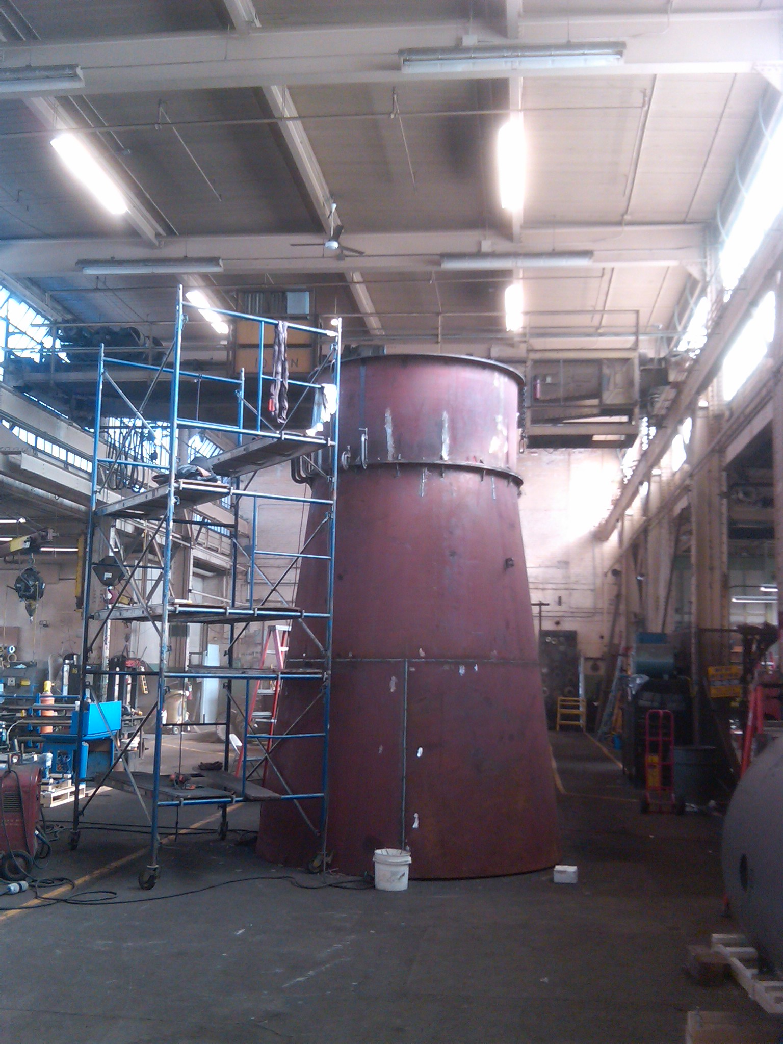
Here is the new No. One pressure casing. It is 169 inches in diameter. The welder is fabricating the floor that the draft tube will be bolted up to and the camel back turbine will be bolted down to.
Here, Cole is barring the No. 2 Generator around while Kenny Smith makes the final alignment and leveling of the unit. Cole is one of our many outstanding employees. He is in training to be an assistant hydro operator at our Woronoco HEP plant. Wayne Roberts, our Wonderful Senior Manager and former operator of the Nantucket Island Power and Light Company,was so impressed with Cole, that after 6 weeks, he asked Davis for an immediate raise in Coles pay rate!!! Go Cole go!!! To do this accurately, you use a dial indicator mounted on a magnetic base. You magnetically hold the base on the rim of one 1/2 coupling. You place the plunger against the rim of the other 1/2 coupling. You slowly turn one shaft while holding the other one stationary. If the two couplings are perfectly concentric, the dial indicator will not move. If they are not lined up to each other, the travel on the dial indicator needle will tell you how far and in what direction to move the generator. If you then place the magnetic base on the face of the first coupling and stretch the two bar linkage over the top of the two couplings so that the plunger is facing, axially back into the second coupling, and you slowly turn one 1/2 coupling while you leave the second 1/2 coupling stationary, if the two couplings are parallel to each other the dial indicator will not move. If the couplings are at an angle to each other you can boost the ass end of the generator base over until the couplings are parallel. Hi Everyone!! The orange crane needed a lot of tender love in order to get it going. The Indian River Unit One, midspan, support bracket has been sitting on the orange crane's deck for 14 months. I need to get it to Industrial Steel and Boiler. I ran out of time today. So how do you get a 600 pound casting off of the crane deck, lowered 6 feet to the ground and loaded into my trustee Ford F-150? Here's how, Will "Fay" Power!!!!!
Will has hooked a chain fall up to the crane boom. He has levered the casting over to the edge of the crane deck. Here he is pushing the casting over the edge while I let down on the chain fall.
Down it goes!!
We hooked a belt up to the trailer ball on the Ford F-150. I am driving it forward while Will lets down on the chain fall.
We installed the red and silver snatch block to the bed hook. We wrapped the belt around the snatch block pulley and back to the chain fall. (I actually have never run a lifting strap through a cable sheave like this. But hey!!! necessity is the Mother of Invention!!!!) Will pulled up on the chain fall and the 600 pound casting got sucked into the bed of the F-150.
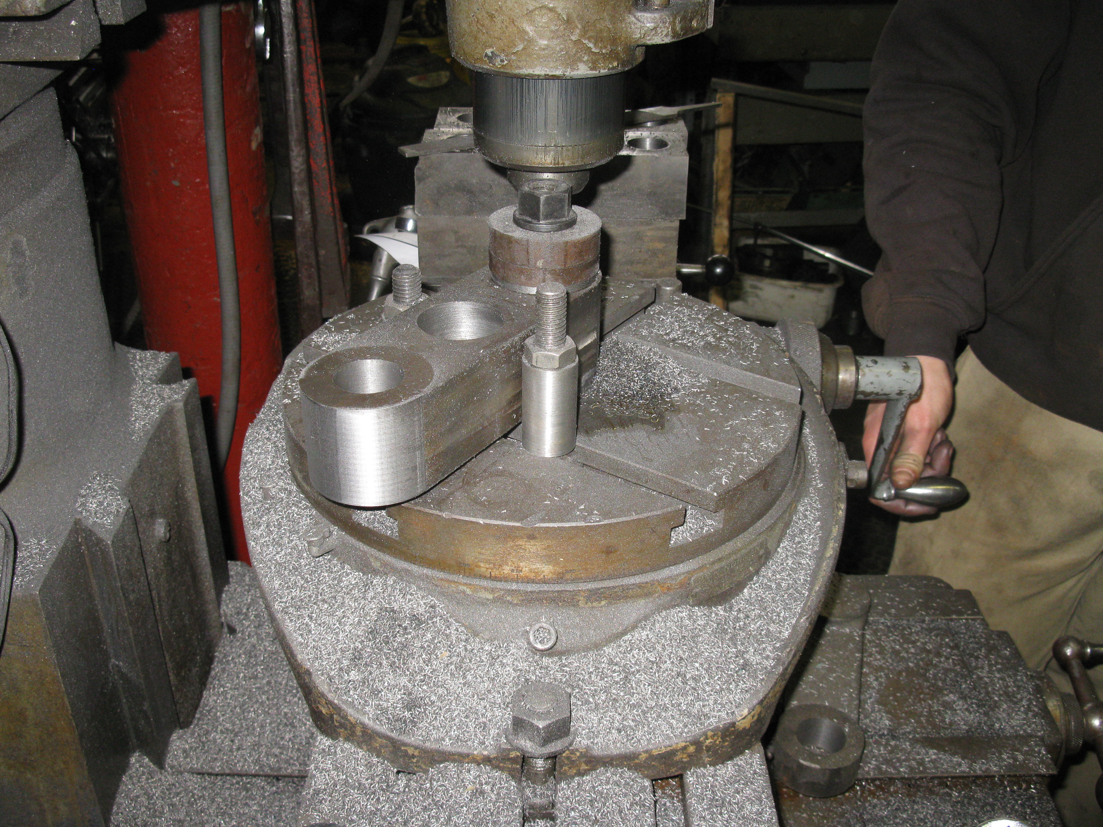
How do you re-machine the top of a vertical generator shaft to renew the surface where the Kingsbury thrust collar presses on? You take an old flat belt pulley hub, you machine most of its bore to fit the worn shaft, you drill a hole at a radial angle down through the hub, you insert a piece of carbide in the hole, you drill and tap the hub so you can install four turning handles and you get four burly workmen to walk around on top of the generator while the contraption drops down the shaft and makes it cylindrical again!!! The advantage is, Jerry got a price of $ 75,000 to take the rotor out of the generator, to turn it on a 72 inch lathe and re-assemble the generator with a 6 week down time. We did the same job in one day and charged him $6,000!!!
Close up view of hand turning device!! Note the rusty shaft beneath the device. The surface should be a mirror finish where we pressed off the "top hat". Since the "top hat" had been loose on the shaft, allowing the generator shaft to rock back and forth and causing considerable vibration, moisture penetrated the fit and the shaft became rusty. It is this surface that is being turned smooth and concentric as the hand turned device that my brother, Warren, The Wizard, is slowly rotated and cuts the shaft surface concentric again. Jerry Olsen was so excited when we got done, he placed a US Quarter, on edge, on the re-assembled unit and it stayed on edge!!! Good job Warren!!!!
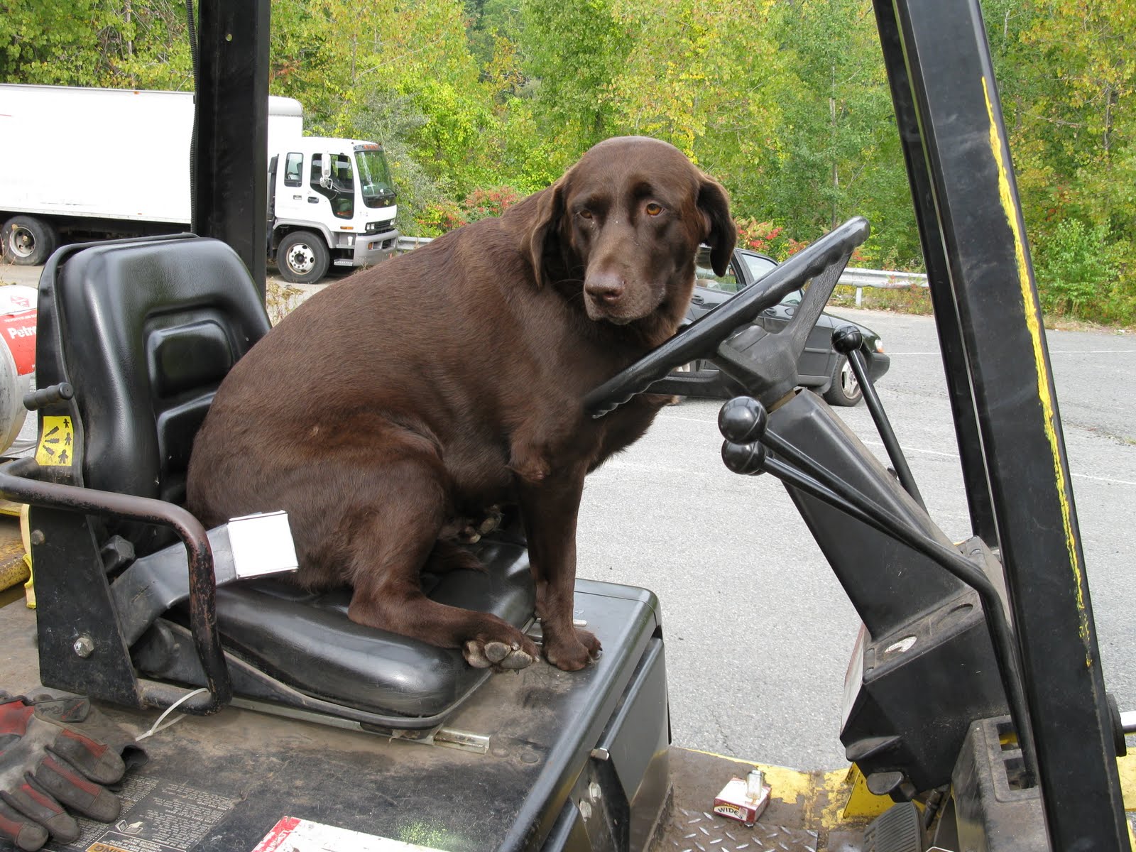
Here, my trustee assistant, Cleo, is driving our big fork lift truck. Sometimes she gets very bossy and starts barking out orders. I forgive all of her faults as she is DOSHA approved!!! (Dog Occupational Safety and Health Agency). It cost over $12.00 in dog biscuits to get her trained!!
Here, my best friend and life long business partner, Warren Davis Hobbs, is seen riding a 36 inch tall, 40 foot long, 15,000 pound I-beam into the abyss at Woronoco Hydro. Davis is certifiably crazy and the hardest worker I have ever encountered. His "can do", "Yankee Work Ethic" is the driving force behind Swift River Hydro!!!! March 15th, 2011, Added "Blade Design" by Nikolai Nikolaevich Kovalev, the premier Kaplan designer of the former Soviet Union. He, Viktor Kaplan and Miroslav Nechleba are the world's greatest designers of hydraulic machinery. I have more of this text if anyone is interested.
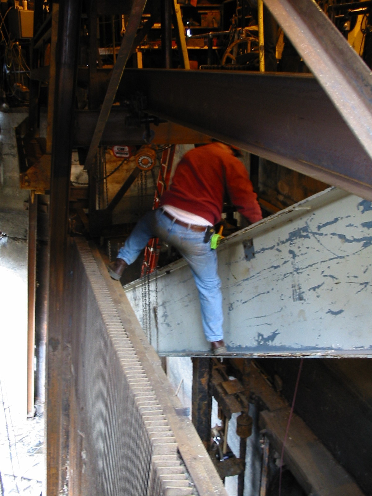
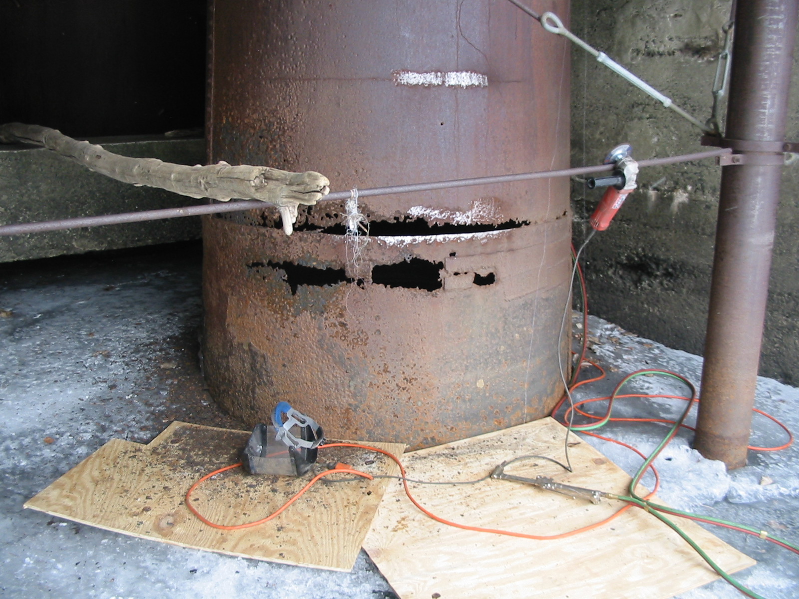
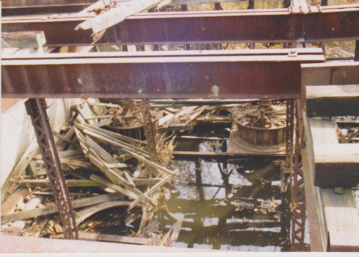
How do you repair a draft tube? You wait until the ice is 18 inches thick and you use the ice for staging! The normal water depth here is about 14 feet. It needs to be that deep because the 1700 kW unit discharges at the back of the pit and the water needs to flow beneath the two smaller units' draft tubes.
May 16th, 2011, Golden Oldies:
Brooke Pennypacker and I inspecting the S Morgan Smith, Type G-1, Unit at Crocker Wheeler Company circa 1982. This unit was installed on 98 feet of head and made 250 KW.
Dayton Globe Iron Works unit at Lincoln circa 1979. This unit was pulled by Rodney Hunt Company and new runners and wicket gates were installed in 1959.
Another view of the Dayton Globe unit at Lincoln. These units drove pulpers and never made electricity.
Billy Poole, Luke Wright and Danny Fay repairing the headrace at Thorndike Upper circa 1995.
The four Leffel Samson units installed on the outer raceway at Schuylerville, N.Y. on the Hudson River, circa 1991. I designed an earthen embankment dam to plug this canal after the machinery was pulled. This raceway was heavily contaminated with PCBs and NYDEC wanted it plugged forever. |
|
|